2021-2022-STHDF
P03-2021-S01-S06:Art easel
Art easel
Authors: Adler Nikodém, Frankovičová Ivana
Introduction
Let us introduce you to our idea for a project.
We want to create an art easel.
Why making an easel when you can buy one? See Ivana's story:
You know, I like art, I like to draw and paint. It's my hobby. Sadly, I don't have much time for art. It takes me a lot of time to create something. I don't have my own art studio like professionals. We currently live in a small apartment and before that we lived in a student dormitory and before that I lived in one room with my brother. I can say that I always have one not very big table for my work and artistic creation. Anyone who has ever tried art knows that time and space are a necessity. The funny thing is that it often takes a lot of time just to make space for work. When you have one table, you use it for many things - the computer, some papers, some books, maybe some food ... and when you decide you want to draw or paint, everything must go off the table. Everything. That means time to clean up the table and time to take out art supplies. Then, for example, you want to devote two hours to art and continue tomorrow. But unfortunately, you often need to use the table in the meantime. That means cleaning up art supplies and putting other things back on the table. And such a vicious circle is created here! No artist enjoys cleaning a table more than drawing or painting.
I've been thinking for a long time about why I don't draw and paint when I want to do it so much. And when I came to the problem I described to you above, it occurred to me ... if I just had an art easel that I could only attach to the edge of the table ... it wouldn't take up lots of space and I wouldn't have to clean my table... win-win!
And I believe I'm not the only one and this idea would be useful to other amateur artists as well.
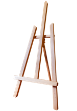
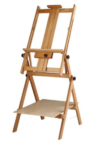
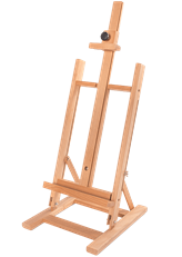
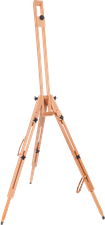
There are a lot of various art easels to buy, but none of them met my idea.
Design
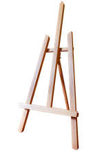
So our vision is a classic wooden art easel with the fact that we attach table clamps to the front legs of the easel, which can be used to attach the easel to the edge of the table.
We need to make sure that the easel is practical. Requirements for the final product:
- possible to attach to the edge of the table
- solid and stable
- suitable size for the table (up to a maximum height of 0.5 m)
- suitable for A6 to A3 canvas
- canvas holder from below, ideally also from above
- adjustable rear leg of the easel
After quick sketch on paper, we quickly made a 3D model without any exact dimensions, so the first design looks like this:
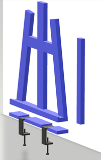
These three parts of the easel you can see, will be attached to each other by metal hinges. We want the main part of the easel to be able to be tilted back. To do this, we need something that supports the main part of the easel at the back and something that will fix the easel at the edge of the table.
The lower part of the easel will be attached to the edge of the table with table clamps. The clamps may or may not be permanently attached to the easel.
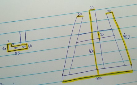
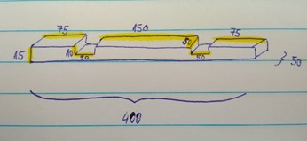
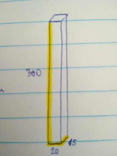
But to make a product, we need to know the exact dimensions of each part of the easel. Each wooden part will be cut separately, so it must also be designed and modeled separately. We also need to know what components we need to buy.
This is our sketch of the wooden parts of the easel with exact dimensions:
3D model
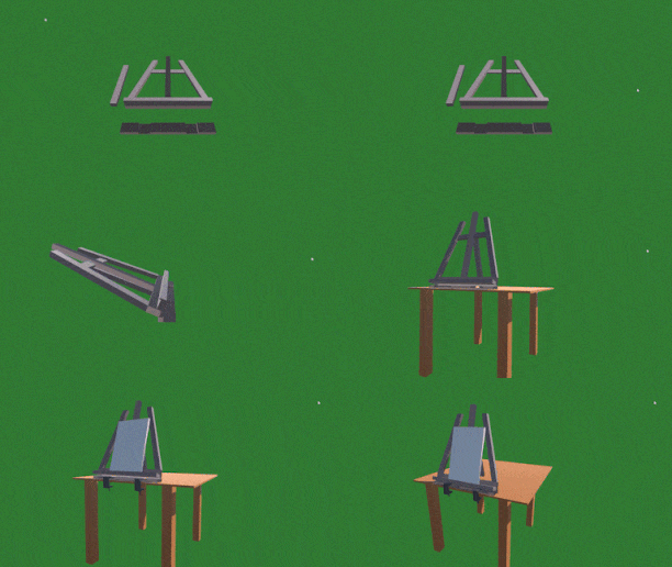
Since we already have the dimensions of the easel defined, we can create a 3D model that will be used for a machine that will carve wooden parts in FabLab.
We used Blender to create our 3D models.
Final product
Our easel will be carved in FabLab. Unfortunately, it is not ready yet.
But we have our home-made metal table clamps ready and they look like this:
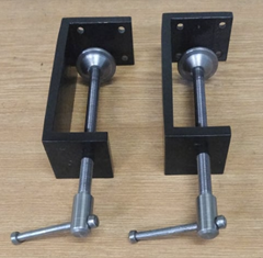
We are sure that after the completion of the product, we will have a great useful product and we are looking forward to it.
- Návštevy: 381
P04-2021-SXx:MusicBox
MusicBox
Intro
A MusicBox is an aic musical instrument in a box that produces musical notes by using a set of pins placed on a revolving cylinder to pluck the tuned teeth of a steel comb. Usually the song which is played on a commercial MusicBox is static. The idea of our solution is to made MusicBox more dynamic, so the end-user can customize pin placement and play more songs.
UC
The image below illustrates main defined use cases and end-users of our solution. Our goul is not to sell the product but rather show the alternative way to construct such thing and contribute to the DIY(Do it yourself) community.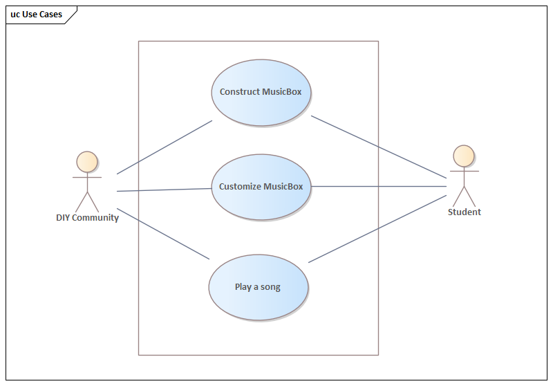
Design
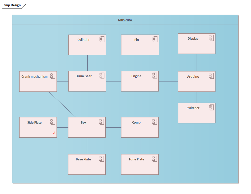
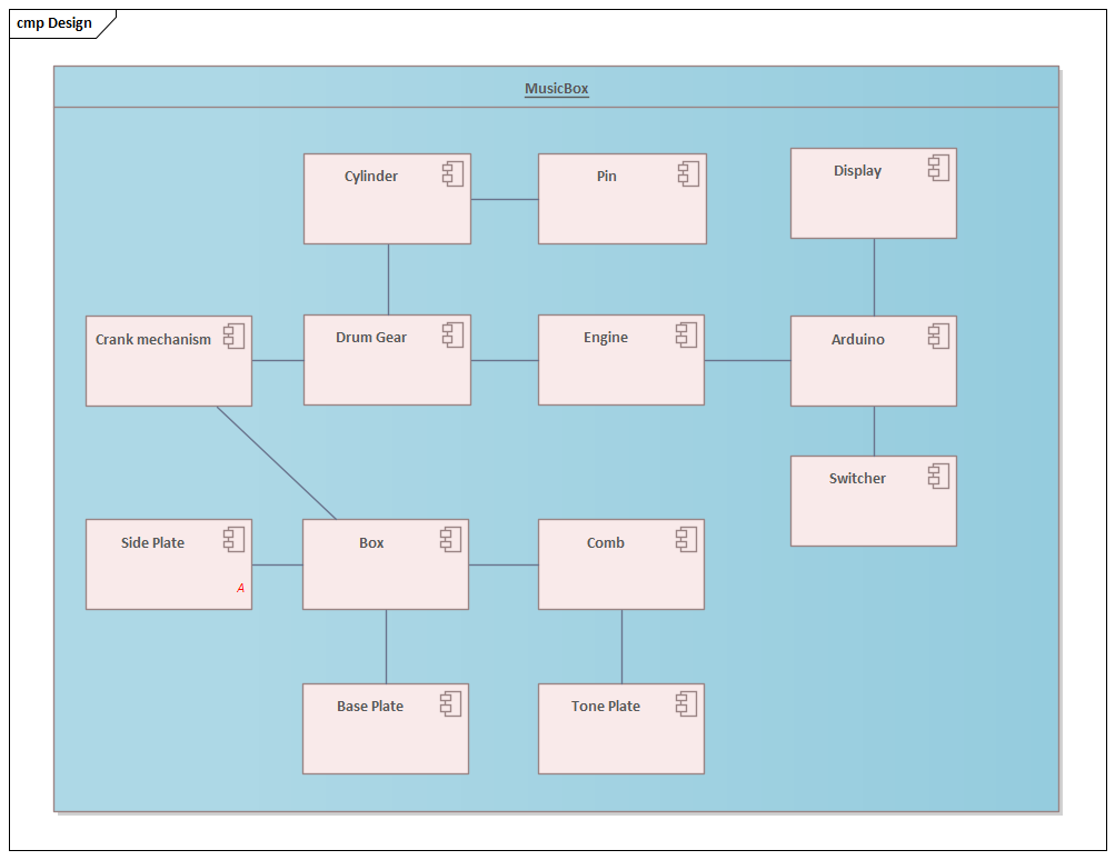
Our proposet design consists of the components that are shown on the image below.
Box
A case is constructed by five wooden plywood plates (base plate, two side plates, middle plate and front plate) joined together with construction wood screws.
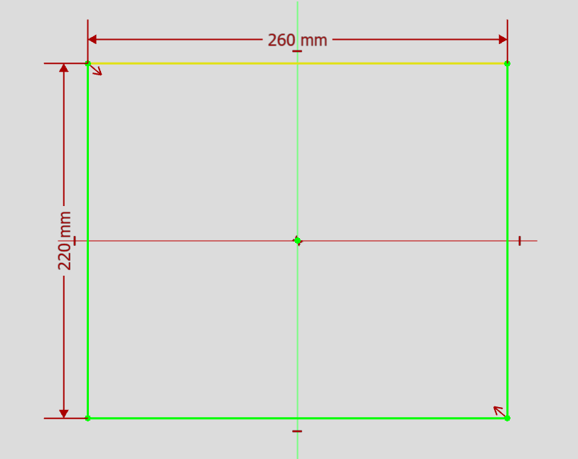
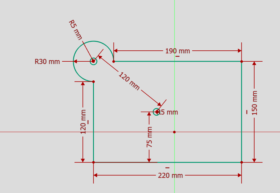
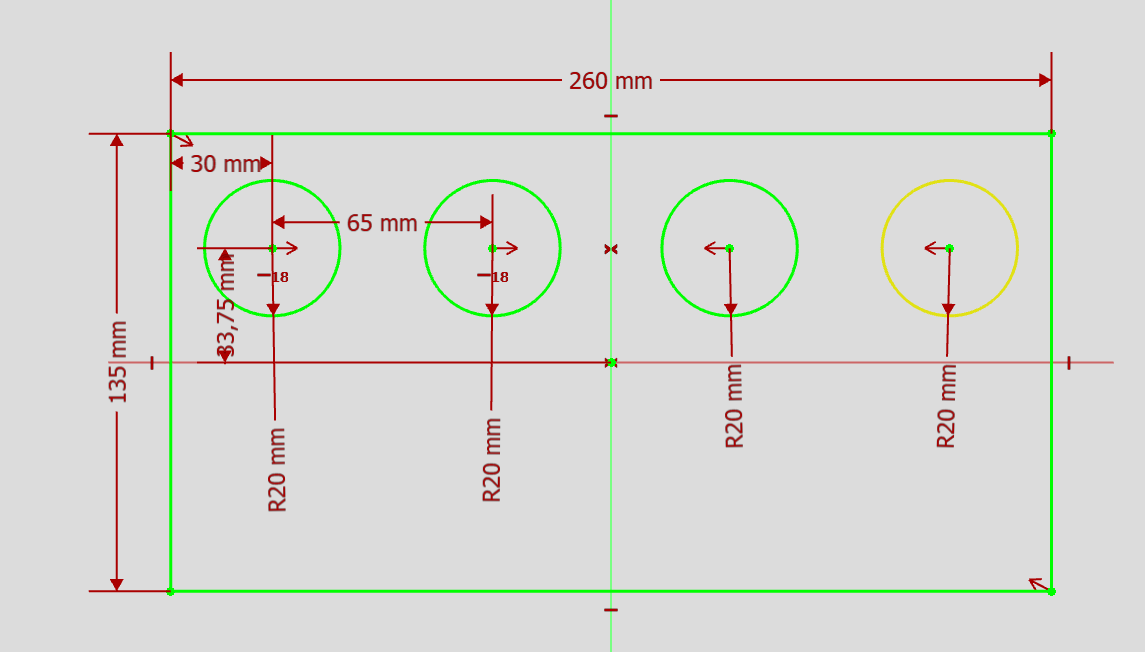
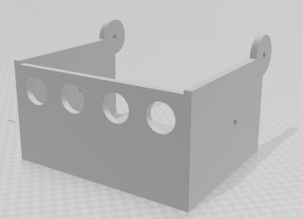
Final parts were cut off from the plywood using laser cutter.
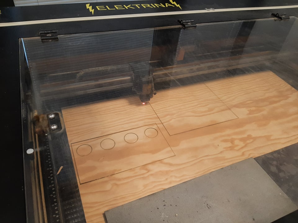
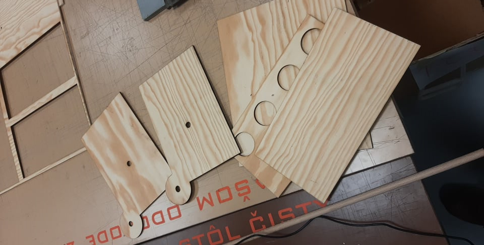
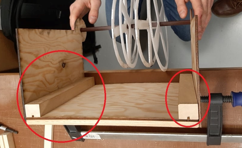
The original design did not expect that the final parts would be that thin, so we had to add support parts for the screws.
Comb
Comb is composed of two main parts:
- 5mm thick metal base plate with carved slots
- Metal plates that are placed into the slot (tuned to play specific tone)
The main plate was constructed in the Craft room using angle grinder, disk grinder and files.The producing of harmonic plates consists of cutting off small parts of material from the edges in order to achieve resonance frequencies of desired tones.
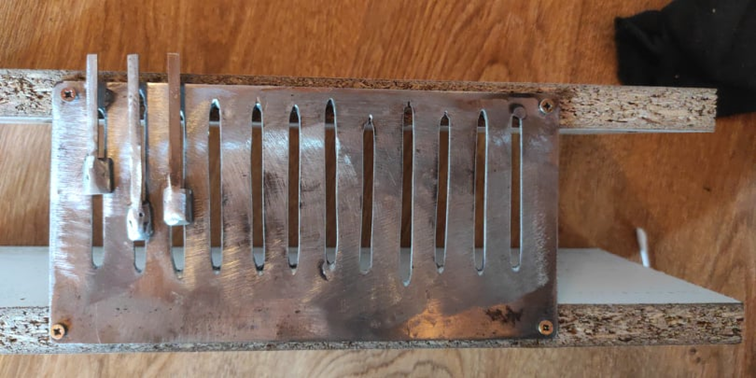
For the validation of final tone resonance we used mobile application for measuring sound signal frequencies.
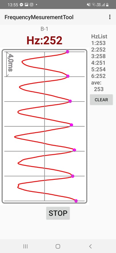
Final comb is able to play 12 notes starting from C4 to B5 (2 octaves).
Cylinder
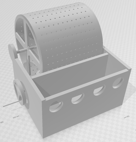
First parameter which was considered when designing cylinder was the number of notes that could be played. We decided to include 32 plates containing holes for pins that could play 12 possible notes at the same time.
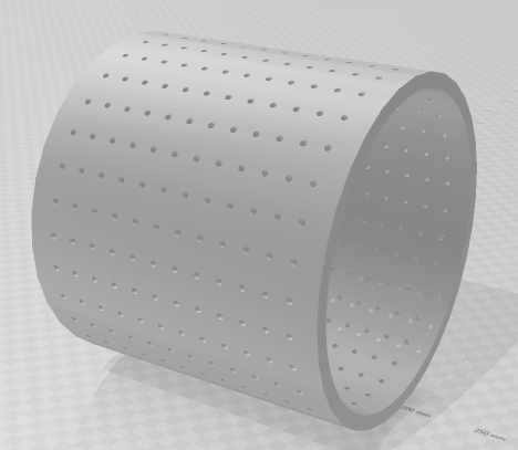
We were not able to print the original design because the dimensions of object were too large for the 3D printer we used:
- lenght: 200 mm
- radius: 110mm
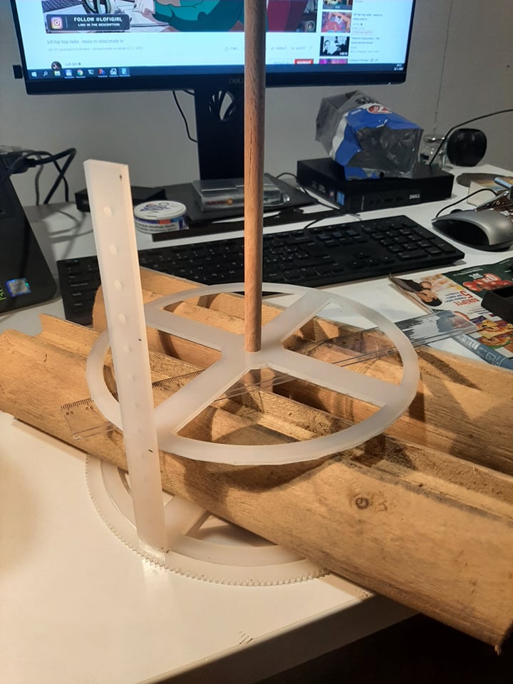
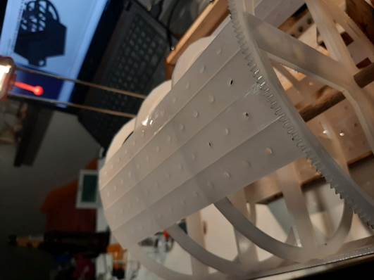
We had to redesign this part. Instead of creating one solid part we decided to split it into individual plates. We also added the support wheels on which the plates sit.
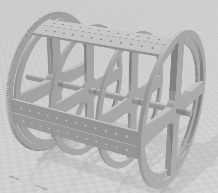
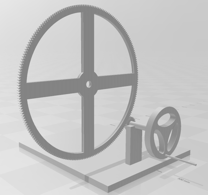
Motion of the cylinder is driven by gear wheel located on the left side.
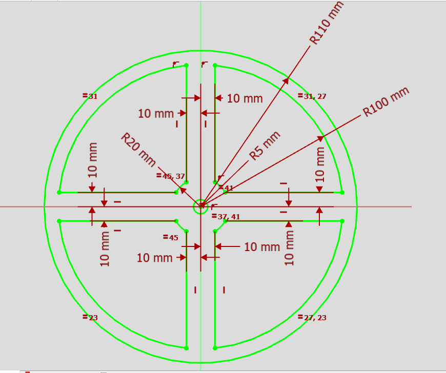
Material used for cylinder construstion is acrylic plexiglass. Cylinder body is filled by joining 32 parts cut out by laser joined with glue.
Pins
While experimenting with the comb we noticed that the best tone was achieved by hitting the metal plate with the same material (...metal :) ). So the idea was to use metal screws as playing pins placed onto the cylinder.
Upon final assembly we noticed that the tone was not sufficient so we experimented with different pin designes.
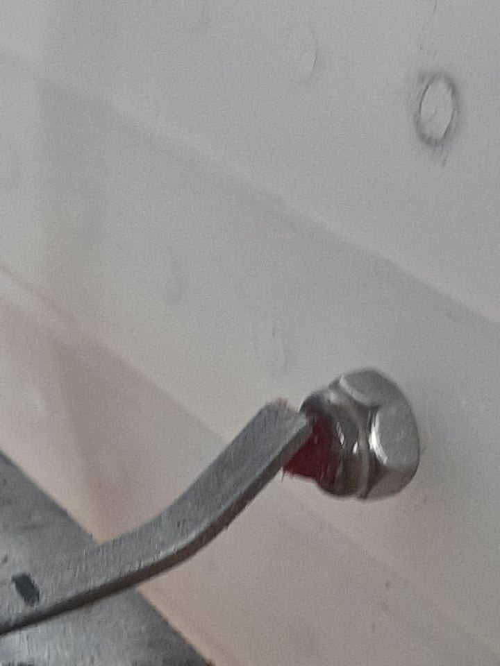
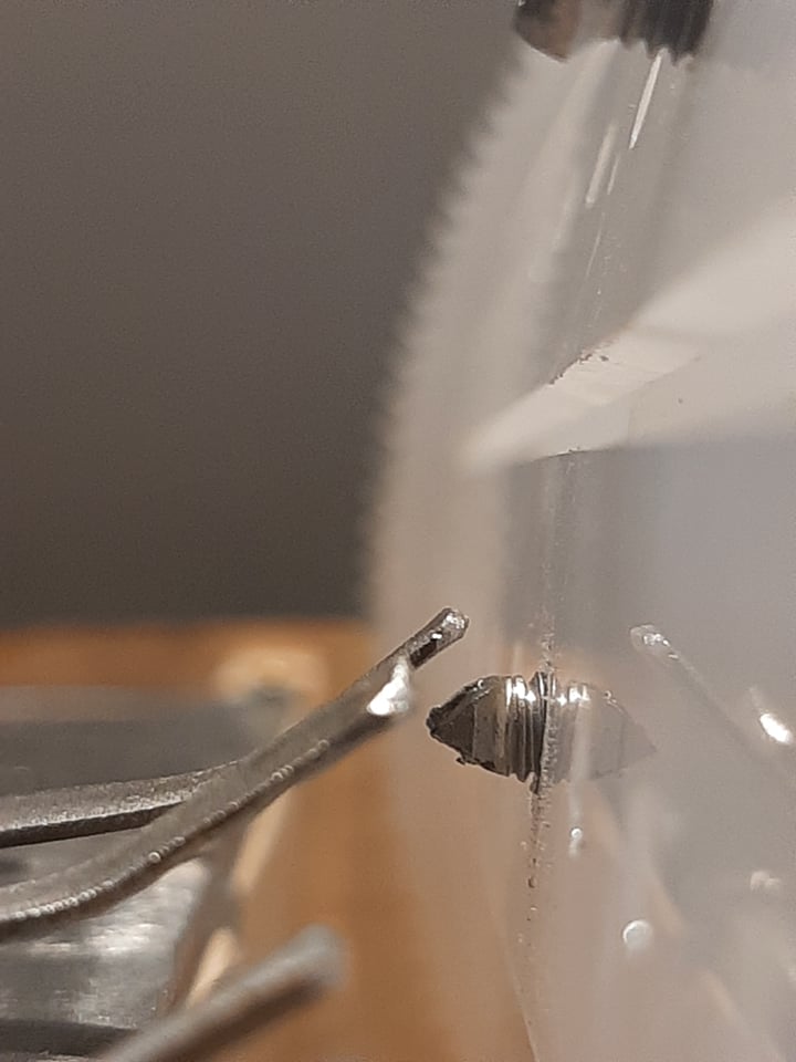
Best result was achieved by using metal screw which head was ground into triangular shape.
Crank mechanism
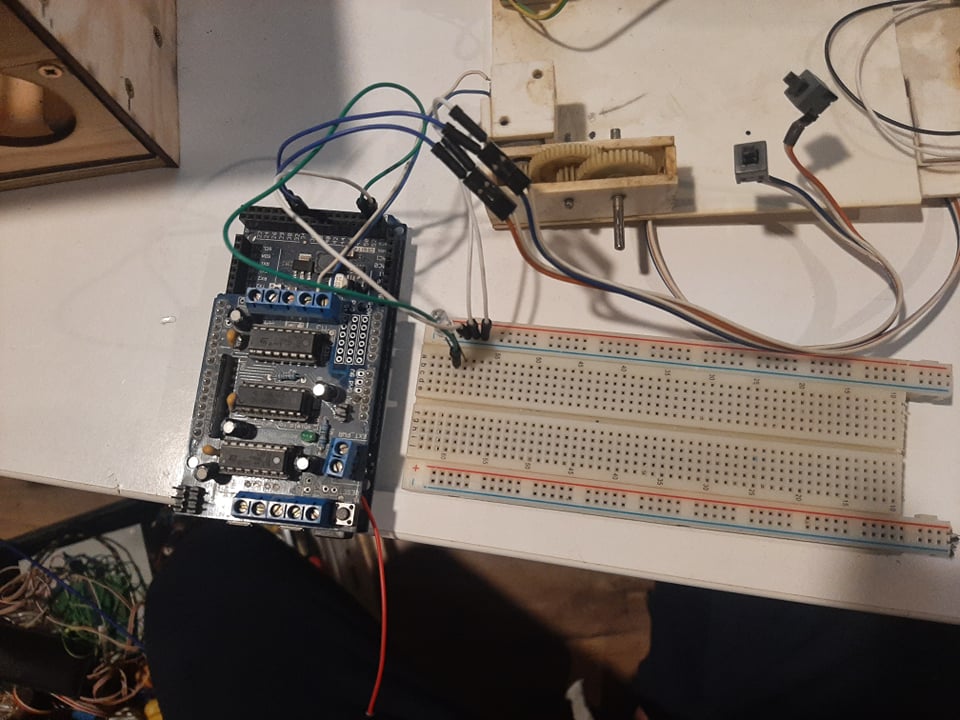
In the original design we planned to drive the cylinder by DC motor (link) controlled by Arduino (with the motor driver shield link). We were not able to achieve the final idea since we were short of available resources at the time of assembling. Motors which were available at this time were not suitable for this purpose.
We decided to constuct the prototype with manual controll of the motion. Redesign consisted of lever with shaft which runs small gear. The gear ratio is 1:10 (for the calculation we used gear generator).
Prototype
3D model of our prototype:
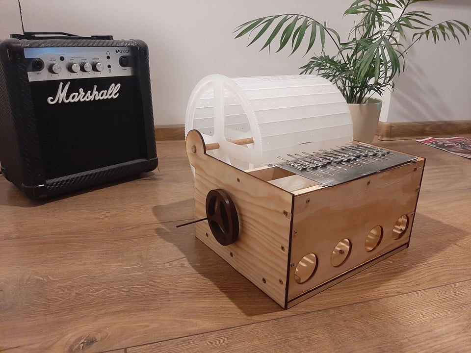
Final funcioning model of our solution is shown on the picture below.
Conclusion
In this article we described the process of analysing, designing and implementing programmable MusicBox. We started with specifying the solution parameters such as dimensions, number of notes and all requested components. Then we created 3D model in FreeCAD 0.19. We started with individual parts that were later assembled into the final model of our product. In order to do this we used Assembly 4 workbench.
During the course of our project we had to redesign the solution multiple times in order to fit the circumstances. Major redesign was needed when we acknowledged the fact that the solution will not be able to print out with the regular 3D printer. Also we had to improvise with the manual drive of a cylinder gear.
In the end we were able to deliver functioning prototype of our solution, which was able to play a simple song.
Links
- Link to EA Model
- Link to Manual (html); Manual (doc)
- Link to Technical documentation (html); Technical documentation (doc)
- Návštevy: 383
P05-2021-S02-S17:SamoGluko
Slovenská technická univerzita v Bratislave
Fakulta informatiky a informačných technológií
Ilkovičova 2, 842 16 Bratislava 4
Systémové myslenie v IT
Projekt - SamoGluko
Akademický rok: 2021/2022, zimný semester
Vyučujúci: Študenti:
Ing. Roman Kazička,PhD. Bc. Ahmed Lotfi Alqnatri
Ing. Jozef Vaško Bc. Jana Lipjanska
Motivácia
Predmet Inovačné podnikanie v IT prináša študentom FIIT STU výbornú príležitosť vyskúšať si vytvoriť vlastné projekty nie len v teoretickej rovine, ale pretaviť ich aj do praxe.
V rámci toho predmetu sme sa zamýšlali nad projektom, ktorý by mohol byť prínosný pre určitú skupinu ľudí. Sme si vedomí, že náš malý projekt nezachráni svet, no rovnako sme presvedčení, že práve malé čiastkové riešenia dokážu v konečnom dôsledku priniesť dobrý spoločný výsledok.
Keďže člen nášho tímu Ahmed trpí ochorením cukrovka, rozhodli sme sa vymyslieť pomôcku pre jeho každodennú nevyhnutnú aktivitu, ktorou je meranie cukru v krvi. Glukomer musí na meranie cukru využiť v priemere aj 7 krát, v dňoch, kedy je jeho hladina cukru nestabilnejšia dokonca až 15 krát. V tejto práci preto detialne opíšeme problematiku, s ktorou sa ľudia, ktorí trpia týmto ochorením stretávajú. Predstavíme niektoré typy glukomerov, ale aj existujúce riešenia, ktoré môžu byť pri meranie cukru nápomocné.
Nakoniec sa pokúsime navrhnúť vlastné riešenie a pretaviť ho do modelov v nástroji Enterprise Architect. Našou snahou je, aby náš návrh bol dobrým vstupom pre riešiteľov, ktorí by mali záujem daný návrh fyzicky vytvoriť.
Problematika
Diabetes je chronický (dlhotrvajúci) zdravotný stav, ktorý ovplyvňuje to, ako naše telo premieňa jedlo na energiu.
Telo cukrovkára buď nevytvára dostatok inzulínu, alebo ho nedokáže využiť tak, ako by malo. Keď nie je dostatok inzulínu alebo bunky prestanú reagovať na inzulín, príliš veľa cukru v krvi zostane v krvnom obehu. Postupom času to môže spôsobiť vážne zdravotné problémy, ako sú srdcové choroby, strata zraku a ochorenie obličiek.
Na cukrovku zatiaľ neexistuje liek, ale chudnutie, zdravé jedlo a aktívna aktivita môžu skutočne pomôcť.
Preto je potrebné kontrolovať hladinu cukru v krvi pomocou prístroja nazývaného glukomer alebo CGM. Takéto meranie je nevyhnutné viackrát za deň, aby diabetik vykonal správne rozhodnutia na udržanie hladiny cukru v krvi v správnom rozmedzí.
Hlavný rozdiel medzi tradičným glukomerom a CGM je v tom, že glukomer potrebuje krv z prsta, zatiaľ čo CGM nepotrebuje pre meranie žiadnu krv. Keďže však CGM nie je ľahko dostupný a väčšinou veľmi drahý, v našom riešení prinesieme návrh pre model, ktorý pomôže diabetikom, ktorí používajú glukomery ako svoj každodenný prístroj.

PCG_0480_use_case
Existujúce riešenia
V tejto časti projektu sme analyzovali existujúce riešenia na podporu problematiky merania cukru v krvi. Väčšina riešení, ktoré sme našli sú najmä na organizovanie jednotlivých komponentov potrebných pri meraní. Aj takéto riešenia sú však prospešné a dokážu byť efektívne vylepšené a doplnené o novú funkcionalitu.
Riešenie č. 1:


|
Výhody |
Nevýhody |
|
funkčné rozdelenie jednotlivých komponentov |
bez aizácie |
|
poklop na umiestnenie malých komponentov |
zaberá veľa miesta na výšku |
|
potenciálne vyhovujúce pre viacero typov glukomerov |
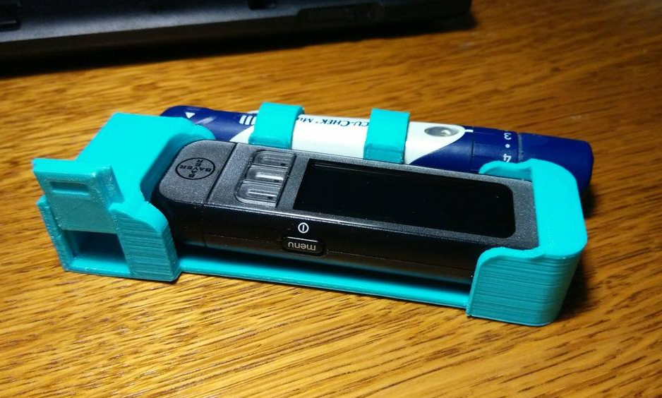
Riešenie č. 2:

|
Výhody |
Nevýhody |
|
kombinujte potrebné príslušenstvo na meranie hladiny cukru v krvi |
bez aizácie |
|
má veľmi jednoduchý dizajn |
nepodporuje rôzne tvary glukomerov |
Riešenie č. 3:


|
Výhody |
Nevýhody |
|
podporuje mnoho veľkostí testovacích prúžkov |
okrem toho, že ide o nádobu na odpad, nemá inú funkciu |
|
veľmi minimalistický dizajn |
nie je možné ho pripojiť k iným komponentom |
Návrh riešenia
Ako sme spomínali v časti problematika, meranie cukru je aktivita, ktorú diabetik vykonáva niekoľkokrát za deň. Zamerali sme sa na situáciu, že túto aktivitu vykonáva v domácnosti. Rovnako netreba zabudnúť na to, že meranie cukru je niekedy nevyhnutné aj počas noci.
Predstavme si situáciu, že celý proces merania, ktorý pozostáva z niekoľkých krokov, musí diabetik vykonať rozospatý, alebo po tme. Práve pre takéto situácie sme sa rozhodli prísť s aizovaným riešením.
Popis procesu testovania
Na vysvetlenie procesu testovania a jeho krokov používame sekvenčný diagram ktorý má nasledujúce kroky:
1. dezinfekcia rúk
2. odobratie testovacieho prúžku zo škatuľky s testovacími prúžkami
3. vloženie testovacieho prúžku do glukomera
4. vloženie čistej ihly do pera
5. pichnutie do prsta a odobratie krvi
6. kvapnutie krvi na vložený testovací prúžok
7. odčítanie výsledku z glukomera
8. vyhodenie použitého testovacieho prúžka


PCG_0475_sequence_diagram_testing
Mechanická pohyblivá časť
Pre navrhnuté riešenie potrebujeme mechanickú pohyblivú časť, ktorá bude vykonávať predpísané pohyby. Pohyby, ktoré bude rameno vykonávať budú za účelom:
- Vybratia testovacieho prúžku zo zásobníka
- Presun testovacieho prúžka do polohy, aby mohol užívateľ kvapnúť krv na prúžok
- Presun testovacieho prúžka do glukomera
- Presun testovacieho prúžka do zásobníka na použité testovacie prúžky
V prvom kroku sme si vytvorili náčrt toho, ako by mohlo naše riešenie vyzerať. V tomto kroku sme si aj ujasnili z akých častí musí pozostávať a najmä aké pohyby musí vykonávať. Nasledujúci obrázok zobrazuje prvý náčrt nášho riešenia.

Existuje niekoľko možností ako potrebný pohyb vykonať. V našom riešení sme sa rozhodli pre pohyblivé rameno resp. pohyblivú ruku, ktorá dokáže vykonávať želaný pohyb a je pomerne jednoducho skonštruovateľná. Na vytvorenie jednotlivých časti nám môže poslúžiť práve 3D tlačiareň, s ktorou sme sa oboznámili na predmete SMVIT.


Pre pohyb jednotlivých častí je možné použiť malé servomotory. Možnosťou je napríklad SG90 Micro Servo Motor, ktorý je malý a cenovo dostupný.


Ako riadiacu jednotku pre takéto riešenie je možné využiť napríklad mikropočítač Arduino. V ňom je možné naprogramovať pozície a polohy ramena tak, aby vykonávalo želanú funkcionalitu.
Pri takomto riešení je následne možné aj prepojenie s mobilnou aplikáciou, čo však v tomto prípade nepovažujeme za nutné.
Popis procesu merania cukru v krvi po implementácii riešenia
Na vysvetlenie procesu testovania a jeho krokov používame sekvenčný diagram ktorý má nasledujúce kroky:
1. zapnutie robota
2. robot (jeho rameno) odoberie jeden testovací prúžok
3. robot vloží testovací prúžok do glukomera
3. diabetik si vpichne ihlu do prsta pomocou pera na to určeného
4. diabetik vloží krv na testovací prúžok vložený v glukomeri
5. glukomer zobrazí výsledok merania
6. diabetik stlačí tlačidlo na ukončenie procesu
7. robot vyberie testovací prúžok z glukomera
8. robot vhodí použitý testovací prúžok do zásobníka na použité testovaci prúžky
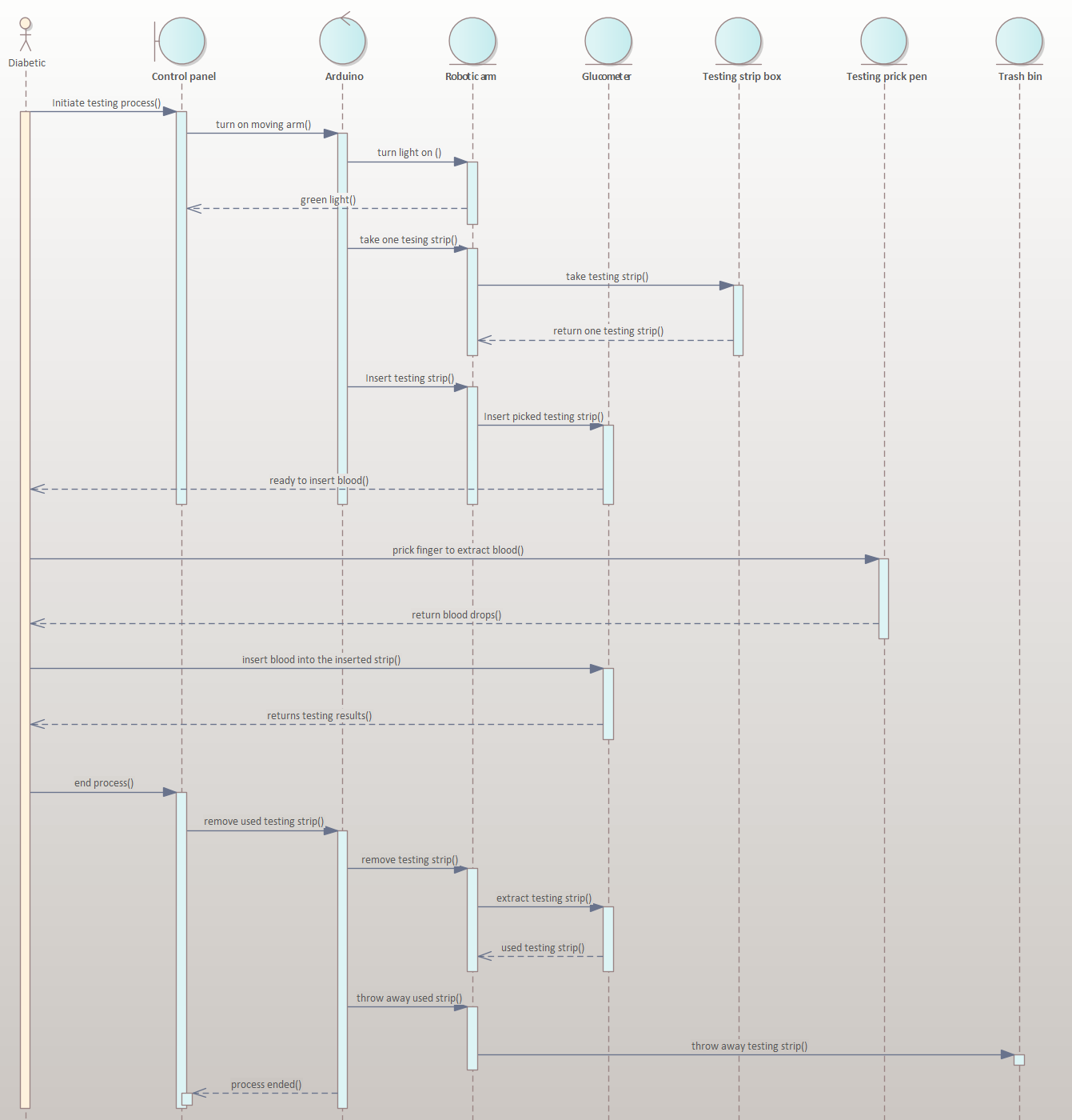
PCG_0476_sequence_diagram_final_model
Existuje veľa potenciálnych vylepšení, ktorými možno vytvoriť robustnejšie riešenie. Počas procesu vytvárania nášho riešenia sme prišli s niekoľkými rozširujúcimi nápadmi a to:
1. vytvorenie aplikácie na ovládanie robota pomocou mobilného telefónu
2. pridanie malej kamery tak, aby dokázala vyčítať výsledok merania z glukomera a preniesť ich tak do aplikácie
3. pomocou kamery tiež môže robot ukončiť proces merania sám po získaní výsledkov
Záver
Cieľom tohto projektu bolo priblížiť problematiku merania cukru v krvi, s ktorou sa ľudia trpiaci ochorením cukrovka denne stretávajú. Naším cieľom bolo priniesť možné riešenie, ktoré by dokázalo tento proces zaizovať. Meranie cukru prebieha niekoľkokrát denne a na rôznych miestach. Naše riešenie sa zameriava na merania, ktoré prebiehajú v domácnosti, kde vytvorený produkt môže mať pevnú pozíciu. Veríme, že náš nárvh by mohol byť pre niekoho, kto sa odhodlá v praxi zaoberať touto problematikou nápomocný.
Prilohy:
Linky pre diabetikov:
- Návštevy: 501
P06-2021-S04-S15-S20-S21:MagicBox
MagicBox
model - FIIT-STHDF/2021-2022/p06/htmlReportMagicBox
PR video - FIIT-STHDF/2021-2022/MAGICbox.mp4
Idea
- separation from loved ones in covid times
- desire to give a gift to loved one
- idea to create magic box as interesting present
Magic box
- lockable box with electrically controlled lock
- mobile application, which is able to connect to the box and lock and unlock it
Possibilities of use
- we want to send a gift securely, so it can be opened only by the giftee
- we want to give an interesting gift that won't be that easy to open
- we want to give a gift to child and we want the child to solve some logical task
- ...
Requirements specification
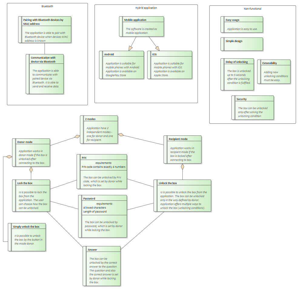
For SW
For HW
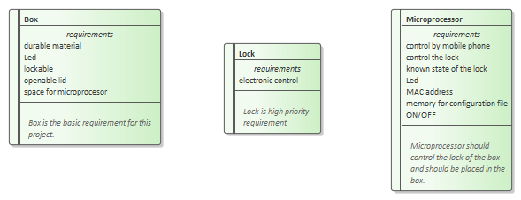
More analysis available in the model.
Design
Box prototype
whole prototype here https://agnicoli.org/FIIT-STHDF/2021-2022/04-Projects/p06/MAGICbox.scad
Wireframes
In model in EA.
In Figma - link can be found in the model.
- Návštevy: 334
P07-2021-Sxx:Armrest Storage Box
Armrest Storage Box
Introduction
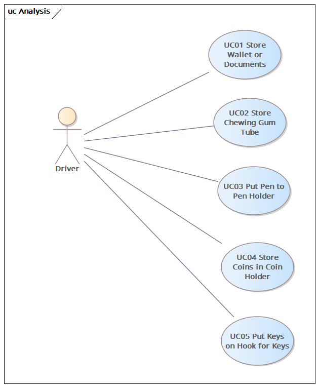
As a final solution, we created a multifunctional and full-featured armrest storage box. This storage box is made specifically for Kia Ceed CD and it should provide user with space for his personal belongings, while ensuring a clean and organized impression while driving.
The image below illustrates multiple usages of our solution.
Motivation
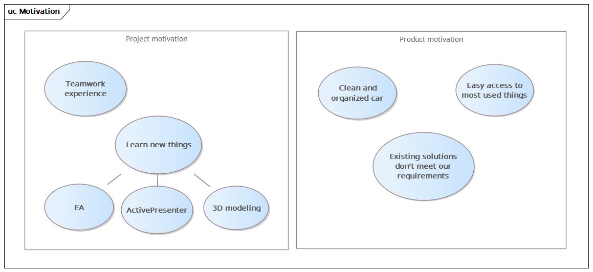
Our main motivation when creating this storage box was:
- to achieve a clean and organized space in the car,
- to have important and often used things within reach while driving,
- improve features of existing solutions, which do not meet our everyday needs and requirements.
At the same time, we wanted to learn new things and work with, for us, unknown technologies.
Existing solutions
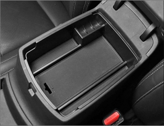
The following images illustrate limitations and weaknesses of existing solutions. These are for example:
- the storage box is too shalow to store larger stuff,
- there are usually missing coin trays and/or these trays are not applicable for euro coins,
- there is often a missing pen holder.
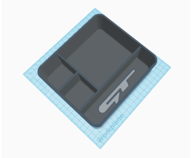
Let's now look at our design.
Final solution
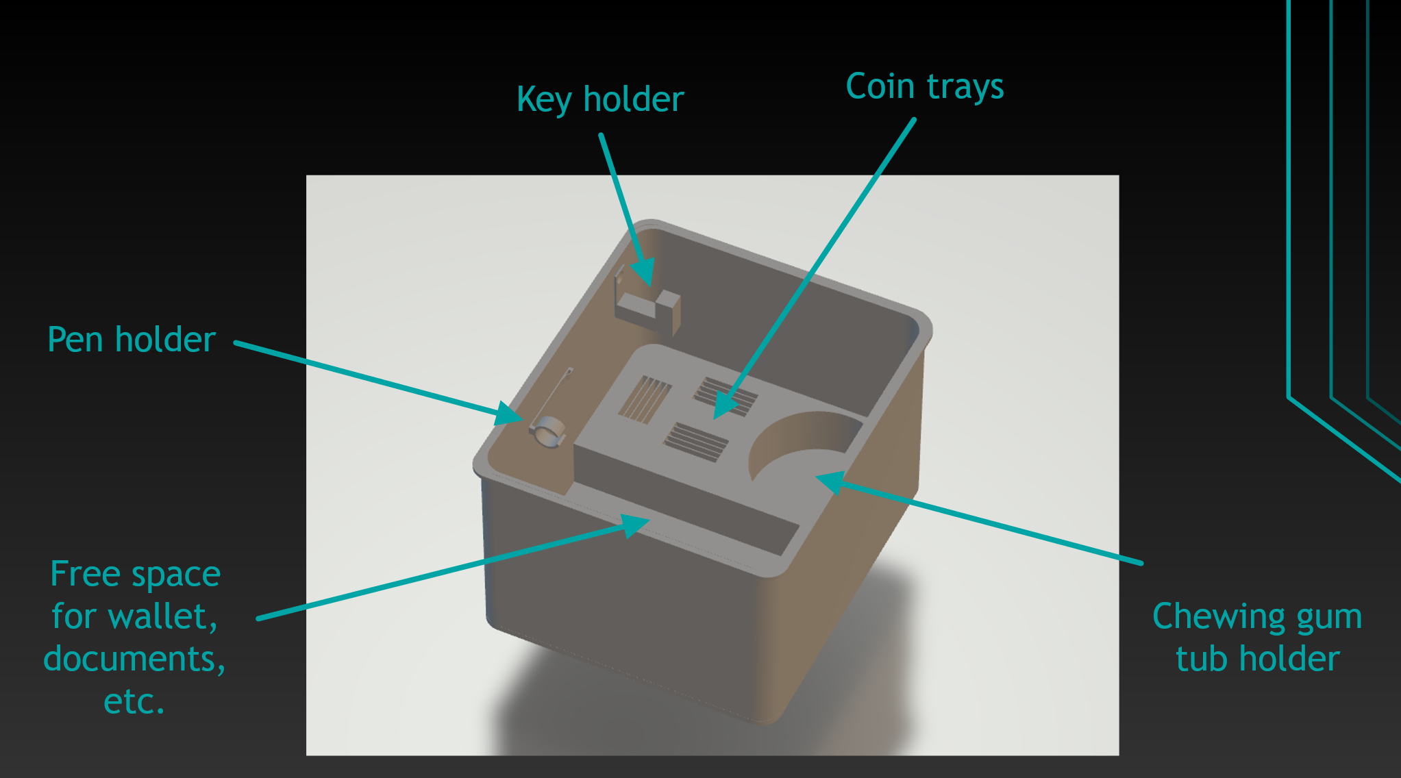
Our final solution has the following features:
- Key holder,
- big enough space for wallet and/or documents,
- chewing gum tub holder,
- coin trays (0.50€, 1€, 2€),
- pen holder,
- slightly deeper than available solutions.
These are the measurements: 14x16x10 cm.
The image bellow illustrates the 3D model of final solution.
Solution materials
- Link to our Presentation
- Link to EA
- Link to wikifactory
- Návštevy: 359
Ďalšie články…
Strana 2 z 3
 2023/2024