SMVIT - Automatic voleyball trainer model
Peter Stríž and Marek Vajda
Our intent is to create small model of machine which can shoot (or throw) balls at variable speeds and under variable angle.
Motivation
We have chosen this topic because we want to enhance our knowledge about 3D printing, CAD programs and IoT technologies, which we believe are going to be one of the leading technologies in the future. The main focus of this project is to find an efective way to build quick and functional prototypes, which can execute our ideas using IoT and 3D printing.
First ideas to solve our problem
The design process typically involves a series of steps, including gathering information, brainstorming, prototyping and testing, and final implementation. In order to create some product, we had to specify what our outcomes should be, so that later we could verify against them if we were succesfull.
Specification:
- create a small model that can shoot balls
- model is 3D printed
- model has 2 motors that spin opposite to each other, in order to shoot balls
- use ESP32 to controll everything
- motors can be easily turned on and off
- support variable speeds between motors, so we can introduce ball spin
Once the product specification was finalized, we began the implementation of the design. We started by creating a rough sketch:
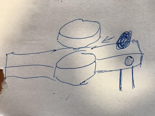
CAD design
Software which we used was Fusion 360, since it provides easy collaboration, parametric desing and relatively easy to use user interface. By using CAD software and 3D printing, we were able to test and make adjustments to our design quite quickly.
This model served as a blueprint for the final product, and we were able to test and make adjustments to the design before actually building it.

At first we designed the upper part that shoots and only after that we focused on designing places to mount our electronic devices.
Later, we used Creality slicer to slice up various parts of our model and convert them to gcode. For 3D printing we used a medium sized 3D printer Creality Ender 5 Plus.
Diagram of physical components
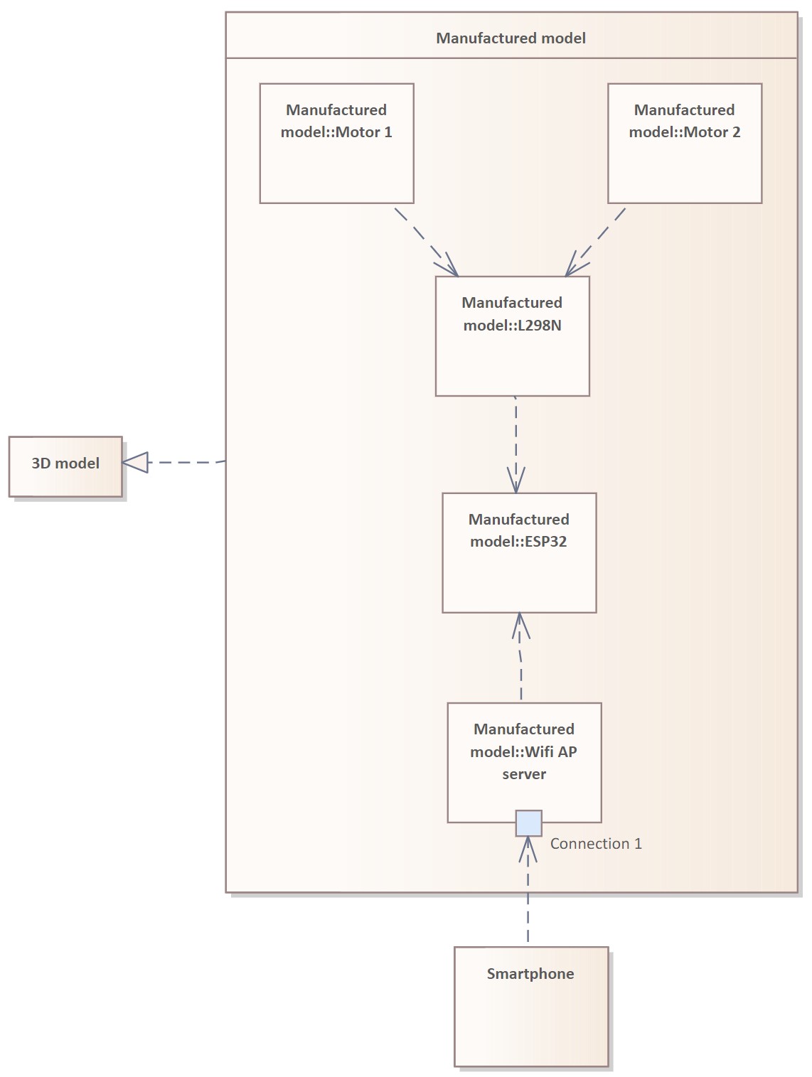
This diagam shows physical components architecture based on our 3D model. Manufactured model is 3D printed CAD model which is described in previous section. There are two electric motors and L298N motor controller with H bridge. L298N serves for controlling the speed and direction of electromotors. ESP32 is also present for controlling the L298N board and providing HTTP server for WEB gui. HTTP server means that this device can be controlled over WiFi with any mobile or PC connected to ESP32s WiFi AP.

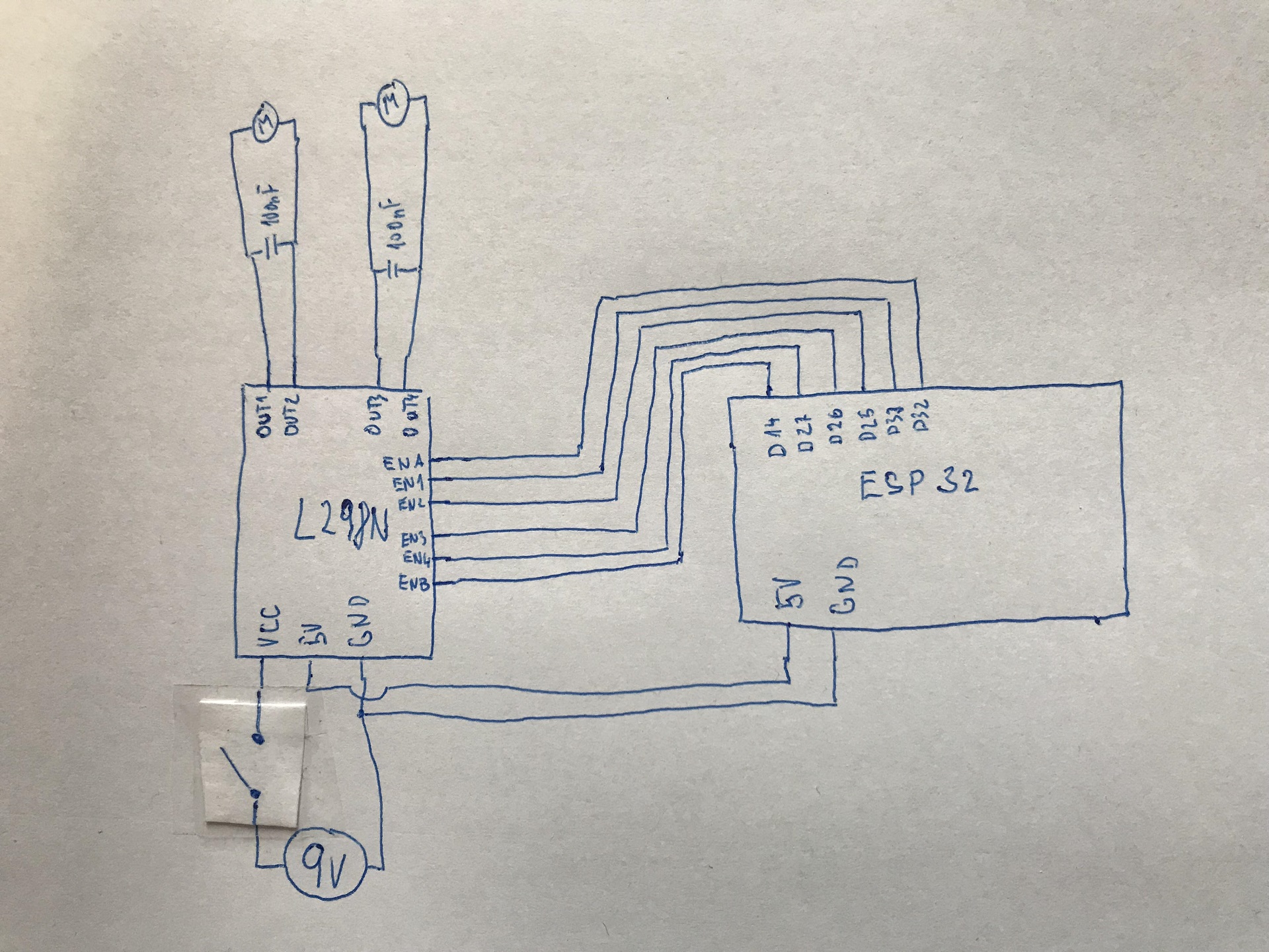
This is the actual wiring diagram we used:
ESP-32 program behaviour
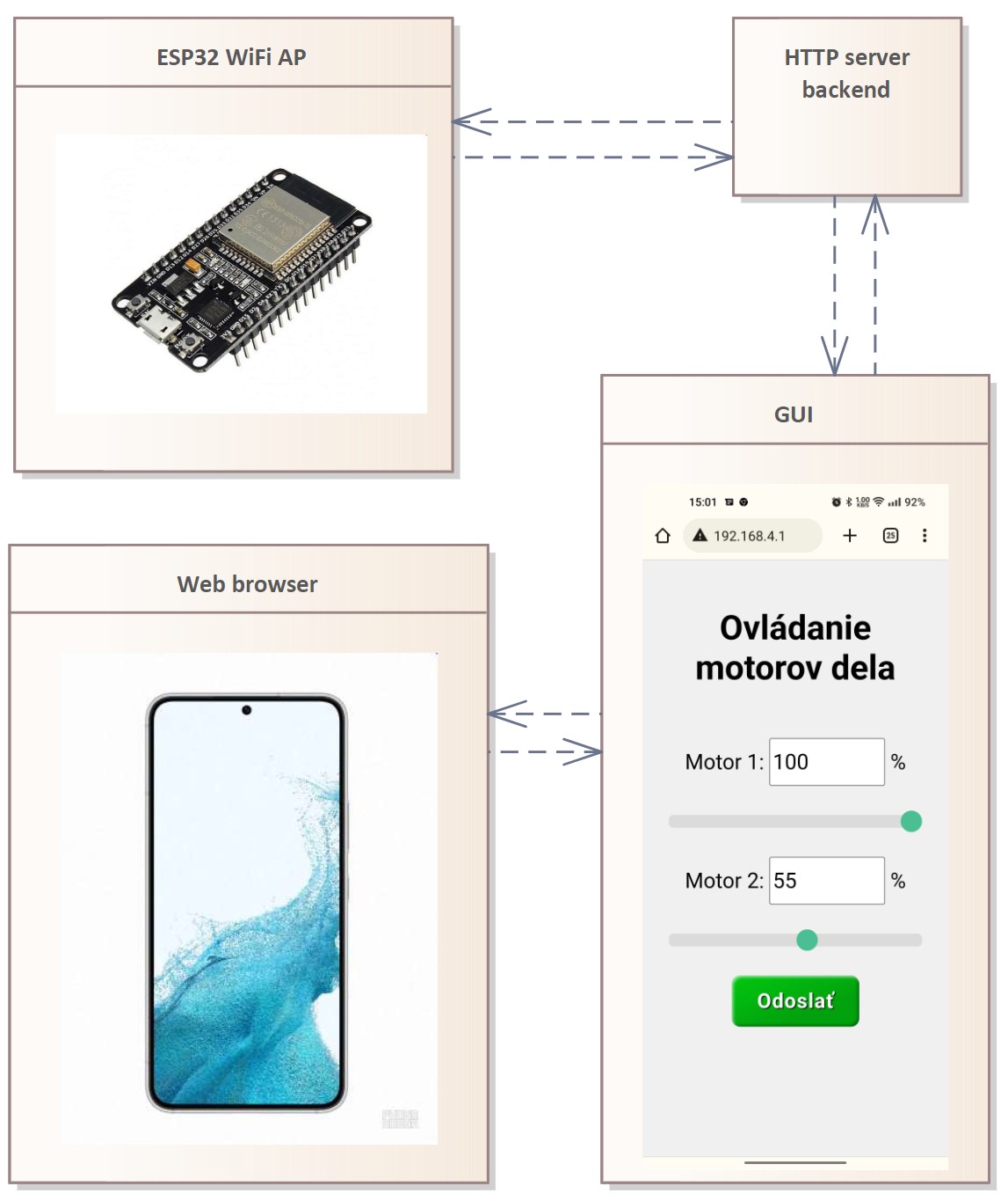
We programmed ESP32 microcontroller to provide a WiFi access point which is used for connection between Smartphone/PC and ESP32. When connection is established, connected devices can access the graphical user interface of simple webapp. Webapp is served by running webserver of ESP32. Gui provides controls of two motors. After HTTP server backend recieves command from gui, ESP32 sends instruction to L298N which sets the motors rpms.
Finished product
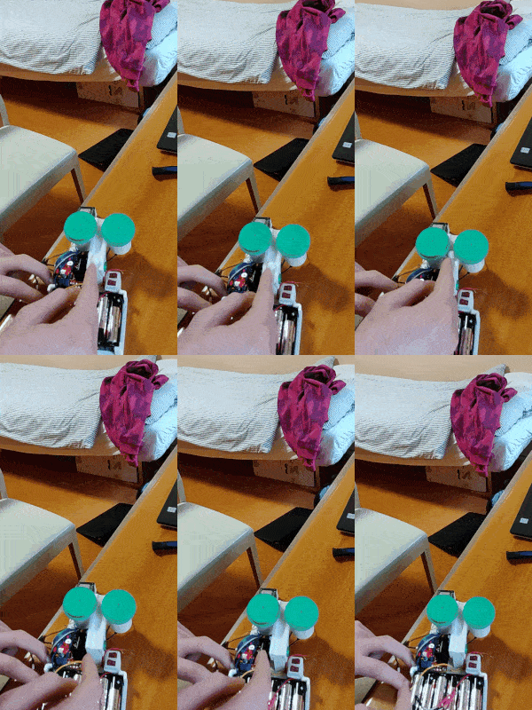
In the end, we were succesfull to create a small model of volleyball trainer that can shoot small balls. We also learned a lot of stuff about 3D printing, wiring stuff and in general about working on a physical devices.
 2023/2024