P02-2022-S09-S11-S17:Chladiaca podlozka
p02
- Návštevy: 508
p02
A doorbell for deaf individuals or those with hearing disabilities can greatly improve their daily lives by providing an alternative method of notification when someone is at the door. This can be especially useful for those who may not always be able to hear a traditional doorbell or may not have someone with them at all times to assist them.
Having various LED devices or vibrating devices placed around the house allows the homeowner to be notified in any room they may be in, rather than being limited to the sound of a doorbell which may not always be audible to them. This gives deaf or hard-of-hearing individuals more independence and allows them to feel more confident in answering the door on their own.
Additionally, a doorbell for deaf individuals or those with hearing disabilities can provide a sense of security by alerting the homeowner to someone at the door, even if they are not able to hear the doorbell. It can also be a useful tool for those who may receive frequent visitors and need an easy way to know when someone has arrived.
Overall, a doorbell for deaf individuals or those with hearing disabilities can significantly improve their quality of life by providing an accessible and convenient way to be notified of visitors at their door.
Using a Raspberry Pi for the Deafinity project can be a good choice for several reasons:
Cost: Raspberry Pi boards are relatively inexpensive, making them a cost-effective solution for the Deafinity project.
Versatility: The Raspberry Pi is a versatile computer that can be used for a wide range of projects. This makes it a good choice for the Deafinity project as it can potentially be repurposed for other uses in the future.
Connectivity: The Raspberry Pi has built-in Ethernet and WiFi connectivity, making it easy to connect to the internet and other devices. This can be useful for the Deafinity project as it may need to send notifications or signals to various devices around the house.
Community: The Raspberry Pi has a large and active community of users and developers, meaning there is a wealth of knowledge and resources available for those working on the Deafinity project using the platform.
Peripherals: The Raspberry Pi has many peripherals available, including LED displays, sensors, and motors, which can be used in the Deafinity project to provide notifications or signals to the homeowner.
Overall, the Raspberry Pi is a good choice for the Deafinity project due to its low cost, versatility, connectivity, and availability of peripherals and community resources.

The Deafinity project has used 3D printing to create two custom boxes: one to house the doorbell button and one to house the LED notification device. These 3D-printed boxes allow for a customized and tailored fit for the specific components used in the Deafinity project. The project required custom boxes to house the doorbell button and LED notification device, and 3D printing allowed for the creation of these tailored and precise fits.
In addition, 3D printing was useful for prototyping in the Deafinity project. It allowed for the creation of prototypes of the custom boxes and other parts, enabling the testing and iteration of different designs before committing to a final version.
Incorporating hinges into the 3D-printed boxes for the Deafinity project allowed for easy access to the electronic components inside while also providing a secure closure. This was made possible through the use of 3D printing, which allowed for the creation of these custom boxes in a single print.
In addition, 3D printing allowed for the precise and accurate placement of the hinges on the boxes, ensuring that they functioned smoothly and effectively. This added a level of convenience and ease of use to the Deafinity project, as the boxes could be easily opened and closed as needed.
Overall, the use of 3D printing in the Deafinity project allowed for the creation of custom boxes with hinges in a single print, enabling a convenient and secure method of accessing the electronic components inside. This proved to be a valuable and effective use of 3D printing in the development of the project.


The doorbell component of the Deafinity project consists of a Raspberry Pi, a battery case, and a mechanical keyboard key housed in a 3D-printed box. These components were assembled as follows:
First, the Raspberry Pi and battery case were placed inside the 3D-printed box. Mounting brackets or other securing methods were used to hold these components in place inside the box.
Next, the mechanical keyboard key was mounted onto the exterior of the box, serving as the doorbell button. The keyboard key was then connected to the Raspberry Pi using the appropriate wiring and connections, allowing the doorbell button to trigger the Raspberry Pi when pressed.
Finally, the box was closed and secured, making sure that all components were securely in place and that the doorbell button was easily accessible from the outside.
Overall, the doorbell component of the Deafinity project was assembled by placing the necessary electronic components inside a 3D-printed box, connecting them, and securing the box to ensure everything was in place and functional.
The LED signal box for the Deafinity project is comprised of a Raspberry Pi, battery case, breadboard, and LED, all housed inside a 3D-printed box. These components were assembled in the following manner:
The Raspberry Pi and battery case were placed within the 3D printed box and secured in place using mounting brackets or other methods. The breadboard was then connected to the Raspberry Pi using the appropriate wiring and placed inside the box. This allowed the Raspberry Pi to control the LED.
The LED was placed in the designated hole on the exterior of the box and connected to the breadboard using the appropriate wiring. The box was then closed and secured, making sure that all components were properly in place and functional.
The LED signal box for the Deafinity project was assembled by placing the necessary electronic components inside the 3D printed box, connecting them, and ensuring that everything was securely in place.

We are the final year students at FIIT STU, Samuel Vanek and Dominik Puk.
As part of the Systems Thinking course, we have designed and created a "Messenger" project which is used to display a desired text between two people via a web application and a display in the form of a matrix LED display.
The solution consists of 3 parts:
In the following chapter, we will present the design of our solution for the individual parts.
Our proposed solution consists of two main component parts:
The Local part of our solution consists of the heart of our system, the ESP12. This ESP uses a matrix display to display information and also has a reset button. The devices will be stored in a fabricated box, which we will introduce later. It consists of three parts.
The Web part of the solution consists of a REST web service used for storing messages from the user part and sending them to the ESP12 for display if requested.
Design of the basic screen for sending messages to the local device.
The screen will have one text field where we can type in the text that is to be displayed on the device. The second will be a button that we can use to send the text itself.
Our box will consist of three parts:
Design of the box in which the LED matrix and ESP module components will be placed, along with dimensions, can be found in the image below.
The top part of the image shows the box from the front. The LED matrix will be placed in the cutout. The pins of the LED matrix will be located in the cutout on the left, from where the wiring will lead to the back part to the ESP module. There will be circular cutouts with a depth of 1.1 cm in the corners of the box. The cutouts will be used to attach and easily remove the front cover.
The lower left part shows the box from the back. The ESP module will be attached to two columns on the left with screws. The pins and wiring from the ESP module will lead into the box, which is why there is a cutout in the right column on the bottom. The wiring from the column cutout leads to the cutout on the right, where it powers the LED matrix in the front. There are cutouts in the corners for attaching the rear cover.
The following image shows the designs for the rear and front covers, which attach to the box and create a whole for placing and protecting the components.
On the left is the design for the rear cover. The cover is filled throughout. There will be holes in the corners for attaching the cover to the back of the box.
On the right is the design for the front cover. In the middle part of the image, the cover is shown from the front and its dimensions correspond to the front of the box so that the entire LED matrix is visible. In the top part of the image, the cover is shown from the back. The cutout in the middle is extended to fit a piece of plexiglass which will protect the LED matrix. In the bottom part of the image, the cover is shown from the top. There are cylindrical protuberances in the corners that will be inserted into the front of the box and secure the cover to the box.
In this chapter, we will describe the individual parts of the solution based on our design.
In this part of the solution, we will describe the process of fabricating the box model along with the iterations that arose from the deficiencies of the previous prototype. We created the box and cover model using the Blender3D modeling tool.
Model of boxView case_model_1.stl @ Wikifactory
Front cover modelView predny_kryt_model_1.stl @ Wikifactory
Back cover modelView zadny_kryt_model_1.stl @ Wikifactory
The image below shows the first printed prototype.
Errors occurred during printing, resulting in the creation of the second iteration model. The design also had to be changed because it proved to be non-functional after implementation.
List of errors in the first prototype:
In the second iteration, we redesigned the front cover. Instead of protuberances, the cover will contain holes and will be attached to the box with screws. This solution does not provide easy manipulation and removable, but it is necessary in terms of strength and quality. The dimensions of the cover are retained from the first design.
We also reduced the height of the cutout for the LED matrix to 3.5, narrowed the columns in the back of the box, and corrected the error in the model that caused the corner to curve.
Final box modelView case_final.stl @ Wikifactory
Final front cover modelView predny_kryt_final.stl @ Wikifactory
3D printing of the individual parts took approximately:
As stated in the design, the web application provides input for the text to be displayed and a button to send the text itself. This text is then saved on the backend of our web application and is made available upon request from the local part.
Node MCU ESP12 - node_techFun
Matrix 32x8 - matrix\_techFunConnection
Description of final product
The local device operates in two modes:
The device is always in AP mode at startup or reset. In this mode, we can connect to the device via WIFI. After connecting, a web page is offered to us, through which we can change the WIFI network to which the device should log in. After saving to this WIFI, the device will automatically log in and switch to the second mode. If the device is within range of the last WIFI network when turned on, the device will immediately switch to Non-AP mode.
In Non-AP mode, the device periodically queries a web service to retrieve the text to be displayed. This text is displayed cyclically on the matrix display. If no text is received from the web service, a default message is displayed.
Team members:


While flying an FPV (First person view) drone one can find themselves in an unfortunate circumstance that requires either an emergency landing to be performed or that can result in a crash. Such circumstances can be classified as:
FPV drones do not come with RTH (Return To Home) functionality as standard as opposed to drones made by DJI. Thus in case of signal loss in most cases is the pilot powerless and can only hope that their drone will survive upcoming crash with the least damage possible.
In the instance in which the drone crashes in a dense forest environment, it becomes difficult for the drone pilot to trace the drone to it’s crash site without any active location monitoring. The task of retrieving the drone can be made all the more difficult by the fact that during the crash of the drone, the main battery can become disconnected thus effectively shutting off the power for the entire drone with all of its modules.
In order to accurately communicate the drone position with the drone operator, a GPS module can be used. It can be installed directly on the drone thus actively monitoring the GPS location of the drone. Then if the location data is transmitted to the drone operator, this data can be then helpful in the subsequent search for said drone with the knowledge of the last known position of the drone. Such GPS module can be also used to create an RTH functionality for the drone.
Another module that the drone will be equipped by is the buzzer module powered from the main battery. Although in the event in which a crash occurs and the main battery is disconnected, the buzzer will become useless. Thus an appropriate proposition is to power the buzzer with an external battery independent of the main battery of the drone.
For the implementaion of the proposed idea will be needed:

GPS and the buzzer module with the external battery will be soldered to corresponding pins of the control unit of the FPV drone. Subsequently these modules will be installed onto the mount and attached to the frame of the drone.


In the Sensor Input section under the Ports tab we will select the port UART3 (Universal Asynchronous Receiver-Transmitter is a computer hardware device for asynchronous serial communication) for the GPS module. Next we will set the bitrate at 57600bps. At last we select the Save and Reboot button.

In the Configuration tab we check the GPS field. As Protocol we choose Ublox and keep the rest default. Then select Save and Reboot.

In the GPS RESCUE section of the Modes tab, we chose the channel number according to the switch on the controller we chose earlier, in our case it is AUX 6. Then select Save.

In the OSD (On-Screen Display) tab we will add all of the elements listed below and position them according to ones prefferences. Then select Save.

In this section we will verify functionality our solution in real life, which is divided into multiple scenarios.
Senario 1: During this scenario, we will simulate a crash where the drone's main battery is disconnected. In principle, we just disconnect the drone from the main battery and wait for the buzzer to respond.
Result: After disconnecting the main battery, the buzzer started beeping within 40 seconds until it was manually turned off. Proof of concept is shown in this video.
Senario 2: In this scenario, we will test the functionality of the GPS module attached to the drone, whether the information provided by this module is shown on the display of the FPV goggles and whether the information about the current position is right. In principle, we take off at a pre-arranged location and note down information about the current location. Then we will verify them via the Google Maps web app.
Result: In the following figure you can see that the display of the FPV goggles shows all the information that we have configured using the BetaFlight program. In the next figure you can see a map with the current position of the drone, which corresponds to the real position of the drone at the time the picture was taken.


Scenario 3: In this scenario we will verify the functionality of the GPS Rescue functionality that we have configured on the drone, the functionality can be tested by flying far enough to cause signal loss or by using a switch that will trigger the GPS Rescue functionality.
Result: When the drone was 441 meters away from the initial take-off position, the signal was lost. Subsequently, the GPS Rescue functionality was activated and the drone switched to FAIL SAFE mode, when the drone took off to the default altitude and automatically began to return to the original take-off position. When the drone was at a distance of less than 50 meters from the initial take-off position, the FAIL SAFE mode was turned off and the pilot took full control of the drone. The sequence of these steps is illustrated in the following figures or in the video.


[1] BetianOfficial Store, „Aliexpress,“ Betian, [Online]. Available: https://www.aliexpress.com/store/2837118. [Cit. 6 November 2022].
[2] Goodluck338 Store, „Aliexpress,“ Goodluck338 Store, [Online]. Available: https://www.aliexpress.com/item/32919224534.html. [Cit. 6 November 2022].
[3] Beitian, „Banggood,“ Beitian, [Online]. Available: https://files.banggood.com/2016/11/BN-220%20GPS+Antenna%20datasheet.pdf. [Cit. 6 November 2022].
[4] blueRC, „iFlight Nazgul5 - GPS Modul Einbauen und in Betaflight einrichten - Tutorial mit Testflug,“ Youtube, [Online]. Available:
Various types of drinks are consumed during many social events. It is often necessary to pour these drinks directly from the bottle, so losses can occur when spilled, or if it is necessary to pour a large amount of drinks, it takes a lot of time. We mainly wanted to solve the spillage problem, which multiplies with the consumption of certain liquids. The result of our project should be a device that, regardless of the type of liquid, can tap the exact amount of the given liquid without losses and always in the same amount by pressing a button.
After deciding on a project, we had to put our design on paper. We already had a plan how it should look, only dimensions needed to be adjusted as we went.
The following image shows our idea from 2 sides:

There should be 2 places on the model, where either shot glass or bottle can be put. For bottles, we wanted to make sure they would not fall out easily, which is why we made a slight reduction for bottle to be placed in. Since bottles come in different shapes and dimensions, we also had to find dimensions of bottles, which we would support. For this, we measured measured dimensions of many different liquor brands available for purchase in Slovakia and created following table:

The table consisted of the volume each bottle had and its dimensions. We made a macro to differentiate the biggest value in each column, which showed us the right size for our bottle holder.
The next picture shows how it should be connected:

For creating the model, we used FreeCad. Even though we have not used this software previously, to our suprise it was fairly easy to get a good grasp of how it works. Since our dispenser should be easily transportable, we chose to do make a 3 part design, which can be easily assembled without any tools necessary.
Assembled model should look like this:

For our dispenser to work properly, it needs following hardware:
We had previous experiences using small pump to pump liquid from one container to other, so we choose the one we know

The pump had following parameters:
Unfortunately, after doing a test run, we have found out that this type of pump is insufficient for our purposes and we need a more powerful type (this type was not strong enough to our surprise). The pump would work if it was directly submerged in the liquid, which is not good enough, since it would drastically reduce types of bottles we could support (bottles usually have narrow neck).
Another problem we came across was with using a board with raspberry PI. We wanted to implement pump control using our input, but the switching transistor has failed while we were doing dry tests, which meant we lost total control of the pump

We used following pins and code on our PI (and ground) for testing purposes:


The result of our project provides a finished 3D model that can be printed and used for final production. In addition to the model, we also designed the connection of individual electronic components and also selected some mechanical components. We found that we undersized the pump and therefore for a functional prototype it is necessary to choose a stronger pump with a stronger source. However, the switching transistor can be controlled via the Raspberry PI as suggested. We plan to continue working to create the first working prototype that can meet the requirements we set at the beginning of the project.
Our intent is to create small model of machine which can shoot (or throw) balls at variable speeds and under variable angle.
We have chosen this topic because we want to enhance our knowledge about 3D printing, CAD programs and IoT technologies, which we believe are going to be one of the leading technologies in the future. The main focus of this project is to find an efective way to build quick and functional prototypes, which can execute our ideas using IoT and 3D printing.
The design process typically involves a series of steps, including gathering information, brainstorming, prototyping and testing, and final implementation. In order to create some product, we had to specify what our outcomes should be, so that later we could verify against them if we were succesfull.
Specification:
Once the product specification was finalized, we began the implementation of the design. We started by creating a rough sketch:

Software which we used was Fusion 360, since it provides easy collaboration, parametric desing and relatively easy to use user interface. By using CAD software and 3D printing, we were able to test and make adjustments to our design quite quickly.
This model served as a blueprint for the final product, and we were able to test and make adjustments to the design before actually building it.

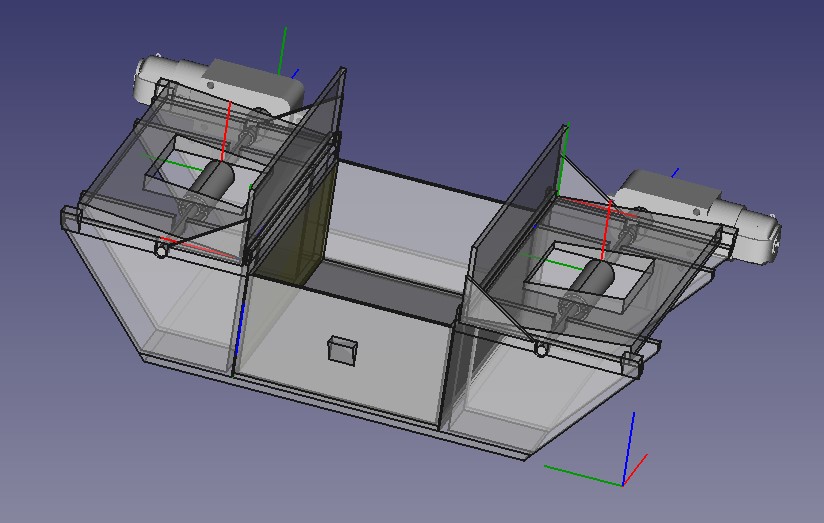
At first we designed the upper part that shoots and only after that we focused on designing places to mount our electronic devices.
Later, we used Creality slicer to slice up various parts of our model and convert them to gcode. For 3D printing we used a medium sized 3D printer Creality Ender 5 Plus.
This diagam shows physical components architecture based on our 3D model. Manufactured model is 3D printed CAD model which is described in previous section. There are two electric motors and L298N motor controller with H bridge. L298N serves for controlling the speed and direction of electromotors. ESP32 is also present for controlling the L298N board and providing HTTP server for WEB gui. HTTP server means that this device can be controlled over WiFi with any mobile or PC connected to ESP32s WiFi AP.


This is the actual wiring diagram we used:

We programmed ESP32 microcontroller to provide a WiFi access point which is used for connection between Smartphone/PC and ESP32. When connection is established, connected devices can access the graphical user interface of simple webapp. Webapp is served by running webserver of ESP32. Gui provides controls of two motors. After HTTP server backend recieves command from gui, ESP32 sends instruction to L298N which sets the motors rpms.

In the end, we were succesfull to create a small model of volleyball trainer that can shoot small balls. We also learned a lot of stuff about 3D printing, wiring stuff and in general about working on a physical devices.

Strana 2 z 3